


Views: 0 Author: Site Editor Publish Time: 2026-09-17 Origin: Site


Achieving a flawless surface finish in 3D CNC machining isn't just about polishing later. It is about eliminating mechanical and software-induced flaws at the source to reduce post-processing costs. Tool marks, chattering, and dimensional inaccuracies quickly turn high-value materials into scrap. You cannot fix a poorly machined surface simply by sanding it aggressively. Evaluating a 3D engraving machine requires looking past top-line speed specifications. You must scrutinize the structural rigidity, motion control, and spindle tolerances. These underlying physical factors dictate actual cut quality.
When you understand these variables, you prevent errors before the spindle even turns. We will explore how hardware stability, spindle precision, and smart CAM strategies work together seamlessly. You will learn to identify equipment capable of holding extremely tight tolerances. We will also discuss reliable methods for verifying machine capabilities before making a procurement decision. This knowledge ensures you invest in hardware capable of true high-fidelity output.
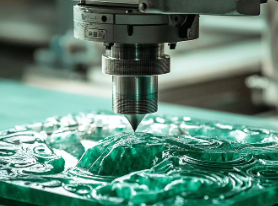
Machine rigidity (frame weight and cast components) is the primary defense against vibration-induced chatter.
Spindle runout (Total Indicator Reading) determines micro-precision; tolerances must align with your material hardness.
In a 3-axis engraving machine, closed-loop servo motors and linear guideways strictly control backlash and positioning errors.
Software-side CAM settings—specifically stepover percentage and toolpath smoothing—are just as critical as hardware specs for achieving near-net surface finishes.
Cutting solid materials generates significant physical resistance. The cutting tool pushes against the workpiece. The workpiece pushes back. This interaction generates intense vibrations throughout the machine structure. If the machine frame lacks sufficient mass, it will flex under these loads. This rapid flexing and bouncing causes the cutter to vibrate against the material. We call this phenomenon chatter. Chatter leaves visible, rhythmic ridges on your finished surface. You must eliminate it to achieve a mirror-like finish.
Machine bed material selection plays a massive role in vibration control. Aluminum extrusions are popular in hobbyist equipment. They are lightweight and easy to assemble. However, aluminum acts like a tuning fork. It amplifies vibrations rather than absorbing them. Industrial production requires heavier materials. Cast iron and heavy steel weldments are vastly superior. Cast iron possesses excellent natural dampening properties. It absorbs kinetic energy before it reaches the workpiece. This translates directly to smoother cuts.
Gantry stability is equally important. The gantry bridge carries the spindle assembly. When the spindle plunges into hard material, upward forces attempt to deflect the gantry. A lightweight, bolted gantry will twist. A heavy, unified gantry bridge resists this twisting force completely. It maintains perfect Z-axis perpendicularity during heavy plunging operations.
When evaluating frame rigidity, follow these specific criteria:
Weight-to-work-area ratio: Heavier machines generally perform better. A dense footprint anchors the machine firmly to the floor.
Stress-relieved castings: Metal retains internal stresses after casting. High-end manufacturers age or heat-treat their castings to relieve this stress. This prevents the frame from warping over time.
Joint construction: Look for welded or cast joints instead of bolted assemblies. Bolted joints loosen and introduce micro-movements during aggressive toolpaths.
Common Mistake: Buying a machine based solely on its cutting envelope. A massive work area on a lightweight frame guarantees excessive chatter in the center of the bed.
The spindle is the heart of any CNC router. Its precision directly limits your maximum surface quality. We measure this precision using Total Indicator Reading (TIR). TIR is the industry standard for measuring spindle runout. Runout refers to microscopic wobbles at the collet. If a collet wobbles by 0.01mm, the error magnifies at the tip of a long cutting tool. The tool effectively cuts a wider path than programmed. This ruins fine details and creates uneven surface textures.
You must match spindle RPM and torque to your specific tooling and materials. Soft materials often allow faster feeds and lower torque. Hard materials demand higher torque to maintain constant chip loads. Spindle speed directly affects how cleanly the tool shears the material.
Consider specialized applications carefully. Ultra-hard, brittle substrates present unique challenges. For example, a dedicated jade engraving machine requires highly specialized spindle configurations. Jade and similar stones shatter easily under stress. They also generate immense heat during friction. Therefore, you need high-RPM spindles running at 24,000 RPM or more. These high speeds take microscopic "bites" out of the stone rather than aggressive chunks. Furthermore, the spindle must utilize a robust water-cooling system. Liquid cooling prevents heat buildup. Excess heat causes thermal shock, which leads to invisible micro-fractures in the finished carving.
Never rely blindly on printed specification sheets. Specs reflect theoretical maximums, not real-world performance. You should always demand documented verification. Ask the manufacturer to perform a dial-indicator runout test during Factory Acceptance Testing (FAT).
Request video proof of the dial indicator touching the inner taper of your specific spindle.
Ensure the needle moves less than the specified tolerance margin while rotating the shaft by hand.
Test the spindle at various RPM ranges to check for harmonic resonance.
Surface quality depends entirely on smooth, predictable movement. A standard 3-axis engraving machine relies on drive mechanisms to translate digital commands into physical motion. Backlash is the enemy here. Backlash is the mechanical slop between a screw and its nut. When an axis reverses direction, backlash causes a brief pause in movement. This pause leaves a visible dwell mark on your part.
You must choose ball screws over lead screws for precision work. Ball screws use recirculating steel ball bearings. They eliminate internal friction and mechanical slop almost entirely. Lead screws rely on sliding friction, which wears down quickly and introduces compounding errors. Ball screws maintain strict positional accuracy, guaranteeing smooth transitions on 3D curves.
Guide rails support the weight of the moving axes. You will encounter two main types:
Round rails: Cheaper to manufacture but prone to twisting under heavy lateral loads. They are unacceptable for high-fidelity 3D surfaces.
Square linear guideways: Profiled rails (from brands like HIWIN or THK) feature precision-ground tracks. They capture bearing blocks tightly. They handle multi-directional forces simultaneously without deflecting.
Motor selection directly impacts surface ridges. Open-loop stepper motors execute commands blindly. If they encounter heavy resistance, they lose steps. The controller never realizes the error. The machine continues cutting slightly off-target, creating nasty surface steps. Closed-loop servo motors solve this problem completely. Servos feature built-in encoders. They constantly monitor their own physical position. If a servo detects a deviation, it corrects the position in milliseconds. Servos guarantee your toolpaths execute exactly as programmed.
Finally, interpolation precision dictates movement fluidity. Your controller handles simultaneous X, Y, and Z movements continuously. Basic controllers struggle with complex math. They introduce micro-pauses while calculating the next coordinate. These pauses cause burn marks and surface pitting. High-end CNC controllers feature advanced "look-ahead" capabilities. They read hundreds of lines of G-code in advance. This allows them to blend movements seamlessly, eliminating hesitation during complex organic curves.
Perfect hardware cannot compensate for poor tooling choices. The cutter determines how the material shears. Ball nose end mills are standard for 3D contours. You must select them carefully based on your substrate.
Flute count matters immensely. A two-flute cutter clears chips quickly in soft materials. However, a four-flute cutter provides a superior finish in hard materials due to decreased chip load per tooth. You also need the right carbide grade and coating. Titanium Aluminum Nitride (TiAlN) coatings protect cutters from extreme heat. Sharp, rigid tools prevent material tearing.
Toolpath strategy dictates your surface smoothness. The relationship between tool diameter and stepover defines your final texture. Stepover is the horizontal distance the tool shifts between passes. Stepdown is the vertical depth of each pass. Large stepovers save time but leave massive ridges called cusps. Small stepovers take longer but yield near-net finishes.
Common Stepover Percentages and Surface Finish Quality
| Stepover Percentage | Cusp Height Size | Primary Application | Surface Quality Result |
|---|---|---|---|
| 40% - 50% | Large | Roughing passes | Highly textured, stair-stepped |
| 20% - 30% | Medium | Semi-finishing | Visible ridges, requires heavy sanding |
| 8% - 12% | Very Small | Final finishing | Smooth to the touch, minimal polishing needed |
| 3% - 5% | Microscopic | Ultra-precision detailing | Mirror-like, near-net shape |
Best Practice: Always balance your time constraints against your polishing budget. A 10% stepover usually offers the best compromise between machine time and post-processing labor.
Software smoothing functions drastically improve results. Organic 3D models consist of thousands of tiny flat polygons. If your CAM software outputs raw linear G-code, the machine moves in jagged, straight lines. You must utilize arc fitting and G-code tolerance settings. Arc fitting converts straight lines into smooth curves. It shrinks file sizes and allows the controller to maintain constant velocity. This prevents faceted, low-resolution curves on smooth models.
Lastly, address clamping and workholding. If your material vibrates, your surface quality plummets. Vacuum tables excel at holding large, flat sheets securely. They distribute holding force evenly across the entire surface. Mechanical clamping works better for thick, irregular stock. Ensure you place clamps close to the cutting area. Unsecured material ends will chatter violently, ruining the finish despite perfect machine hardware.
Selecting the right equipment requires a systematic approach. You must define your success criteria clearly before talking to sales representatives. Do not accept vague promises like "high quality." Instead, map your requirements using measurable metrics.
Use Ra (roughness average) and Rz (mean peak-to-valley height) values to define your acceptable surface finish. Map these exact values to the machine's guaranteed repeatability specifications. A reputable 3D carving machine manufacturer will guarantee specific mechanical repeatability tolerances. If your required finish demands sub-micron tolerances, you immediately filter out lower-tier machinery.
Never base your decision on generic display models. Showroom samples often receive heavy hand-polishing before display. You need reliable proof of capability. Demand a custom sample test. Send the manufacturer your own CAD file. Ship them the exact material you plan to process. Ask them to record a continuous video of the machining process. This proves the machine's true feed rates, rigidity, and unpolished finish quality. It exposes any weaknesses in their spindle or motion control systems.
Scalability requires careful thought during the shortlisting phase. You may only need flat 3D relief carving today. However, future projects might involve complex, cylindrical geometries. Consider factoring in the addition of a 4th-axis rotary indexer. Adding a rotary axis later can sometimes compromise Z-axis clearance or bed stability. Ensure the machine architecture supports 4th-axis integration natively without sacrificing baseline 3-axis rigidity.
Surface quality is not an isolated metric. It is a holistic outcome born from a well-engineered system. Frame mass neutralizes vibration. Spindle precision dictates the true path of the cutter. Strict motion control systems, powered by closed-loop servos and linear rails, execute instructions without deviation. Optimized toolpaths then utilize this rigid hardware to shear material cleanly.
You cannot achieve exceptional finishes if any single element fails. Therefore, you must take proactive steps before finalizing your purchase. Compile a strict technical requirement checklist. Document your limits for spindle runout, acceptable frame materials, and motor types. Hold manufacturers accountable to these metrics. Request custom sample cuts using your specific materials. By analyzing real-world test results instead of marketing brochures, you guarantee your investment will meet your exact surface finish requirements.
A: For fine detailing, acceptable spindle runout (Total Indicator Reading) should fall strictly below 0.01mm (0.0004 inches). Anything higher causes the cutting tool to wobble microscopically. This wobble magnifies at the cutting edge, leading to inaccurate dimensions, poor surface finish, and accelerated tool wear. High-precision tasks demand strict adherence to these sub-0.01mm limits.
A: Standard wood routers use air-cooled spindles and lightweight frames. Jade carving requires fully enclosed cutting areas to contain coolant. The spindle must be water-cooled to prevent overheating and thermal shock to the stone. Additionally, it needs to sustain extremely high RPMs (often exceeding 24,000) to grind through brittle hardness without causing micro-fractures in the material.
A: No. Software can optimize toolpaths to reduce sudden cutter loads and minimize aggressive plunge moves. However, it cannot overcome physical deflection, frame vibration, or mechanical backlash. If the physical structure flexes under cutting forces, the tool will chatter against the workpiece regardless of how well the CAM software calculates the G-code.
A: Cusp height refers to the microscopic ridges left behind between parallel tool passes on a 3D surface. When a round ball nose mill steps over to make its next cut, it leaves a tiny unmachined peak. You minimize cusp height by reducing the stepover percentage in your CAM software, usually setting it to 8-12% for final finishing.


