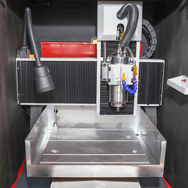
The 3-axis engraving machine stands as the definitive workhorse for commercial job shops and serious hobbyists alike. You will find it cutting everything from plywood cabinets to intricate brass plaques. However, its fixed-spindle geometry creates strict project boundaries you cannot ignore. Mechanics dictate its precise function. The spindle moves fluidly along the X, Y, and Z axes. It never tilts or rotates. This fixed orientation means the tool must always approach the material from above. Buyers frequently misunderstand these rigid geometric limits. This confusion leads to wasted materials and highly inefficient workflows. Our goal is to provide a realistic evaluation of practical, scalable products. We will examine which product categories generate consistent profit on a standard three-axis setup. You will also discover exactly when your operation requires a hardware upgrade. Understanding these limitations prevents costly hardware mismatches. Let us explore the exact boundaries of this foundational manufacturing technology.
Key Takeaways
Ideal Geometry: Best suited for 2D profiling, 2.5D contouring, and single-sided 3D topographies (where no undercuts are required).
Core Applications: Highly profitable for flat-stock processing, custom signage, architectural panels, and precise mold-making.
Specialty Niches: Capable of intricate work like jewelry masters and stone carving, frequently utilized as a CNC jade carving machine.
Hard Limitations: Cannot machine undercuts, complex overhangs, or continuous multi-sided geometries without manual part repositioning.
Defining the Geometric Sweet Spot for a 3-Axis Engraving Machine
Buyers often overestimate what fixed tooling can achieve. Conversely, some operators underestimate modern software capabilities. Clarifying your geometric limits prevents costly equipment mismatches. Your spindle orientation remains strictly vertical. You must understand how this physical reality impacts your final designs. While vendors often market this equipment as a 3D engraving machine, you should master 2.5D first. In 2.5D machining, the tool moves simultaneously along the X and Y axes. It maintains a locked Z depth during each pass. Once a layer finishes, it plunges deeper. We use this approach for pocketing, profiling, and chamfering flat parts. True 3D surfacing involves continuous, simultaneous movement across all three axes. Top-down 3D surfacing works beautifully for undulating landscapes or soft organic curves. The "Line of Sight" rule forms your fundamental physical constraint. The cutting tool needs uninterrupted top-down access to your material. Imagine a light shining straight down from the spindle collet. If a feature sits in a shadow beneath an overhang, the machine cannot reach it. The bit only cuts what it can strike directly from above. You cannot bypass this rule through software settings. Modern simulation tools provide immense value here. Before cutting physical material, you should run virtual CAD simulations. The software highlights unreachable areas in red. It calculates exactly where the shank of your bit might rub against deep cavity walls. Understanding this tool clearance prevents broken end mills. You must account for the bit diameter, flute length, and collet nut width. If a deep cavity requires a tool longer than your safe Z-axis travel limit, a standard setup cannot execute the job.
High-Volume Commercial Projects: Flat-Stock and Signage
High commercial margins require maximum bed utilization. You want minimal operator intervention during the cut. Avoiding manual part flipping guarantees faster, predictable production cycles. Flat-stock processing fits this economic criteria perfectly. Architectural panels present massive scaling opportunities. You can easily operate your setup as a dedicated relief carving machine. It processes MDF, solid wood, and composite acoustic panels efficiently. Tooling realities dictate your specific workflow here. You will typically run aggressive roughing passes using flat end mills. Afterward, you deploy tapered ball-nose bits for smooth, high-resolution finishing passes. These continuous surfacing paths take time but yield premium decorative products. Custom signage delivers excellent return on investment for small shops. V-carving remains a highly profitable staple for commercial wooden signs. You can also mill clear acrylic for edge-lit LED displays quickly. Directional wayfinding signs require crisp, precise lettering. A rigid frame handles these acrylic and plastic jobs flawlessly. Consider modern nesting and cabinetry workflows. Flat-pack furniture relies entirely on standard vertical routing. Three-axis systems represent the absolute industry standard for cutting cabinet carcasses. They drill precise shelf pin holes and cut interlocking dados in single automated setups. Best Practices for Flat-Stock Processing:
Secure large stock using a high-flow, multi-zone vacuum table.
Utilize modern nesting algorithms to reduce expensive material waste.
Select compression bits for clean top and bottom edges on veneered plywood.
Use single-flute bits to prevent melting when cutting cast acrylic.
High-Precision Niches: Stone, Jewelry, and Metals
You must evaluate your machine's rigidity carefully. Delicate or exceptionally hard materials demand specific hardware configurations. You need the correct spindle speed, proper runout tolerances, and suitable coolant systems. Stone processing requires highly specialized hardware adaptations. When operated as a CNC jade carving machine, robust water cooling is mandatory. You cut memorial plaques or intricate jade ornaments using sintered diamond tooling. These specific setups must manage intense friction heat continuously. They also generate highly abrasive dust. If stone slurry enters your linear guide blocks, they will fail prematurely. You must ensure your machine features heavy-duty bellows to protect moving parts. Jewelry wax masters demand microscopic detailing. You can create intricate two-part molds or wax positives for investment casting. These tasks necessitate premium, high-tolerance spindles. Low runout is absolutely critical for success here. Even minor spindle vibrations will snap fragile micro-end mills. Vibrations also ruin delicate jewelry prongs before casting even begins. Aluminum and brass prototyping is highly viable. However, frame your expectations realistically. You can engrave and mill soft metals successfully. Your machine frame must possess sufficient mass and rigidity. Cast iron or heavy epoxy granite bases absorb vibrations well. They drastically outperform lightweight aluminum extrusions during metal cutting. To succeed in high-precision niches, follow this ordered checklist:
Verify spindle runout using a precision dial indicator before cutting.
Install a dedicated mist coolant or continuous flood coolant system.
Upgrade to precision ER collets to grip smaller micro-tooling securely.
Isolate the machine frame entirely to prevent external shop vibrations.
Assessing the Boundaries: When 3-Axis Falls Short
We must provide clear, skeptical-friendly advice regarding limitations. Knowing exactly when not to buy prevents severe buyer's remorse. A three-axis setup simply cannot perform every manufacturing task. The undercut problem halts many ambitious projects immediately. Aerospace components often feature complex internal fluid channels. Modern mechanical impellers possess overlapping blade geometries. Complex statuary involves intricate folds and deep horizontal overhangs. These designs strictly require 4-axis rotary or full 5-axis systems. Your vertical spindle cannot reach underneath a protruding ledge. It will simply crash into the top layer attempting to reach the bottom. Many operators attempt manual flipping to solve this limitation. They use metal indexing pins to machine two-sided parts. This manual workaround introduces significant production risks. Tolerance stacking becomes a serious, compounding issue. Every manual flip introduces a tiny physical alignment error. These microscopic errors compound quickly across multiple setups. You might notice a visible seam where the front and back cuts meet. Furthermore, manual intervention increases labor costs dramatically. If you must flip parts constantly, commercial scalability plummets. You lose the primary automation benefit entirely. Fixture complexity also skyrockets when pushing these boundaries. Attempting to hold organic, curved shapes for secondary operations requires custom soft jaws. You must machine custom cradles just to hold the part securely. This preparatory work consumes hours of unbillable time. If you spend three hours designing fixtures for a one-hour cutting job, your profit margins disappear. Shops prioritizing agility avoid these complex setups. Common Mistakes to Avoid:
Accepting jobs with severe undercuts on a standard flatbed setup.
Assuming advanced software can bypass physical spindle access limits.
Underestimating the manual labor time required for precise part indexing.
Failing to calibrate bed tramming, resulting in uneven depths on flipped parts.
Implementation Risks and Scaling Considerations
Implementation realities extend far beyond the initial machine purchase. What else must you budget for to guarantee project success? Bare hardware represents only one part of the operational equation. Your dependency on CAM software is absolute. Your physical equipment operates only as well as the generated toolpaths. Producing efficient, crash-free paths requires excellent software training. Advanced 3D surfacing demands capable, specialized CAM packages. These programs often carry expensive licensing fees or annual subscriptions. Do not treat your software pipeline as an afterthought. It dictates your machining speed and surface finish quality directly. Workholding strategies heavily dictate your project success rate. Your chosen project type defines your required hold-down method. Vacuum tables dominate high-volume flat-stock processing. Precision machine vises secure thick metal blocks effectively. Custom poured fixtures hold irregular jade pieces or delicate wax masters firmly. Environmental controls represent another hidden implementation factor. High-speed routing generates massive volumes of airborne particulate. Wood dust poses severe respiratory and fire hazards. You must budget for an industrial dust collection system with an adequate CFM rating. Conversely, metal and stone cutting introduces coolant management. You need proper enclosures to contain mist and splash. Slurry from stone carving requires settling tanks to prevent drain clogs. Ignoring these environmental requirements leads to rapid machine deterioration. Evaluate spindle power and linear guides properly. Shortlist your machines based on your primary cutting material. Wood processing favors high-RPM spindles for fast feed rates. Stone and metal require lower RPMs but demand significantly higher torque.
Machine Configuration Comparison Chart
Primary Material
Recommended Spindle
Ideal Workholding
Frame Requirement
Plywood & MDF
High RPM, Air-cooled
Multi-zone Vacuum Table
Welded Steel Tube
Soft Metals (Aluminum)
High Torque, Mist Cooled
Precision Vises / T-Slot
Cast Iron / Heavy Steel
Stone & Jade
Water-cooled, Sealed
Custom Waterproof Jigs
Epoxy Granite / Cast Iron
Conclusion
The standard vertical-spindle router remains completely unmatched for flat-stock processing. It handles the vast majority of architectural reliefs and top-down surfacing projects perfectly. It provides the most cost-effective, scalable solution for these specific two-dimensional and single-sided three-dimensional geometries. When deployed correctly, it becomes the most profitable tool on your shop floor. You should audit your top three intended products immediately. Run a thorough CAD simulation for each product design. Check carefully for hidden undercuts, inaccessible features, or tool collision risks. Request material-specific test cuts from your chosen manufacturer. Review these physical samples under proper lighting before finalizing your capital expenditure. Verifying surface finish in person confirms whether the machine's rigidity matches your exact production standards.
FAQ
Q: Can a 3-axis engraving machine do full 3D sculptures?
A: Only if the sculpture can be split into flat-backed halves and glued together later. You might also succeed if you use complex manual repositioning techniques. However, true 360-degree continuous carving requires a rotary axis. The fixed vertical spindle cannot reach underneath the material or carve around complex overhangs without part rotation.
Q: Can I upgrade a 3-axis machine to a 4-axis later?
A: Yes, many controllers support adding a rotary A-axis. You can plug this into the Y or X-axis driver. Some systems allow a standalone fourth drive. However, buyers must ensure their controller board has this native capability. Your CAM software must also support continuous 4-axis toolpath generation to make this upgrade work.
Q: What is the learning curve for a 3D engraving machine?
A: The physical machine operation is straightforward. You will master the interface quickly. The true learning curve lies in CAD design and CAM processing. Generating efficient, crash-free toolpaths takes practice. Expect two to four weeks of dedicated learning for complex relief carving. Simple 2D profiling takes only a few days to understand.
Anhui Yuhan Numerical Control Technology Co., Ltd. was established in 2014 and is a modern science and technology enterprise integrating research, development, production, and service.